- Benz 230 Battery
- |
- Benz 230 Control Units
- |
- Mercedes Electronic
- |
- Technical Info
- |
- Car Tech Info
- |
- MicroTronik
Mercedes Benz 230 Battery Control Unit
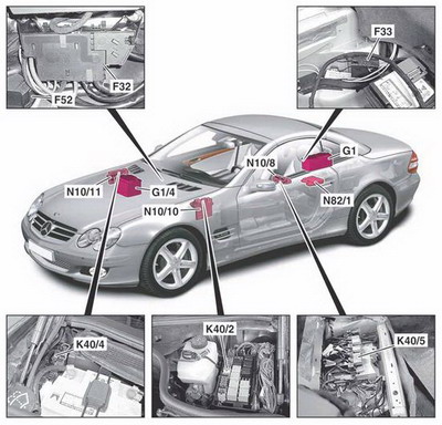
Electrical system components
Battery Location
Charging and Jump Start
electrical system structure
Electrical system components
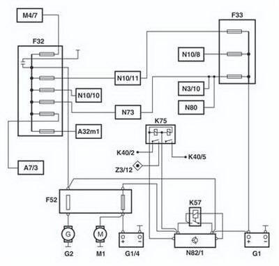
· F32 Front prefuse box· F33 Rear prefuse box
· F52 Fuse through-plating
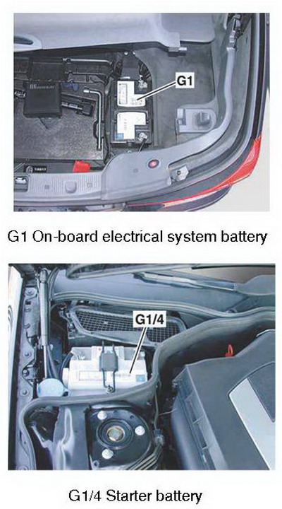
· G1 On-board electrical system battery
· G1/4 Starter battery
· K40/2 Driver-side fuse and relay module
· K40/4 Passenger-side fuse and relay module
· K40/5 Rear fuse and relay module
· N10/8 Rear SAM control unit
· N10/10 Driver-side SAM control unit
· N10/11 Passenger-side SAM control unit
· N82/1 Vehicle power supply control unit
On-board electrical system components
Features of the on-board electrical system for Model 230 has a two-battery electrical system, consisting of a starter battery (G1/4) in the engine compartment and an on-board electrical system battery (G1) in the trunk.The task of the starter battery (G1/4) in normal operation is to provide the energy required for the starting procedure.
The on-board electrical system battery (G1) supplies all the electrical consumers in the vehicle, even when the vehicle is idle.
The separation of the on-board electrical system into a starter battery circuit and an on-board electrical system battery circuit serves to preserve the starting ability of the vehicle.
On-board electrical system management
The on-board electrical system in model 230 is managed by the battery control unit (N82/1). It uses the measured voltage and temperature values to evaluate the state of the battery and initiates measures to stabilize the on-board electrical system if necessary (e.g. consumer shutoff).Fault messages in the on-board electrical system
The white fault message "Electrical consumers switched off!" (consumer shutoff) is displayed under the following conditions:• Voltage of on-board electrical system battery (G1) < 10.6 V (shutoff stage 1)
• Voltage of on-board electrical system battery (G1) < 10.2 V (shutoff stage 2)
The red fault message "Battery Symbol, Service Required" is displayed under the following conditions:
• Circuit 61 not present (engine running)
• Vehicle power supply control unit (N82/1) defective
• Coupling relay defective or wiring harness to coupling relay defective
• Power supply to EIS [EZS] control unit (N73) (circuit 30z) defective
• Fuse in front prefuse box (F32) defective
Battery
OverviewOn-board electrical system battery (G1)
Location
The on-board electrical system battery (G1) is located under the spare tire cover on the right.
Starter battery (G1/4)
Location
The starter battery (G1/4) is located at the rear of the engine compartment on the right in front of the firewall.
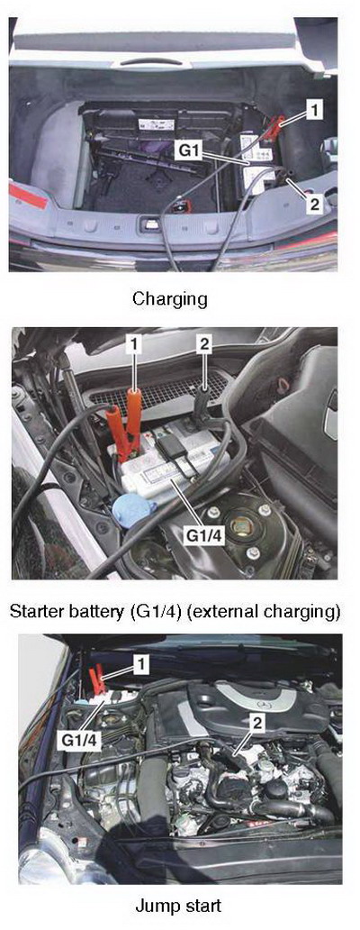
Charging
On-board electrical system battery (G1)• Check condition of on-board electrical system battery (G1).
• Connect positive clip (1) of charger to positive terminal of on-board electrical system battery (G1).
• Connect negative clip (2) of charger to negative terminal of on-board electrical system battery (G1).
• Charge on-board electrical system battery (G1).
· 1 Positive clip
· 2 Negative clip
· G1 On-board electrical system battery
Starter battery (G1/4) (external charging)
• Check condition of starter battery (G1/4).
• Connect positive clip (1) of charger to positive terminal of starter battery (G1/4).
• Connect negative clip (2) of charger to negative terminal of starter battery (G1/4).
• Charge starter battery (G1/4).
· 1 Positive clip
· 2 Negative clip
· G1/4 Starter battery
Starter battery (G1/4) (internal charging)
The starter battery (G1/4) is charged by the vehicle power supply control unit (N82/1) under the following conditions:
• Engine on (circuit 61 signal present)
• Voltage of on-board electrical system battery (G1) > 11 V
Recharging occurs with current and voltage regulation (U = 13.5...16.6 V). The charging current is limited to max. 15 A. The charging time depends on the battery temperature (calculated from outside temperature and engine temperature) and lies in the range of 12....180 min.
Jump start
• Connect positive clip (1) to positive terminal of starter battery (G1/4).• Connect negative clip (2) to body or engine ground (e.g. engine block lifting lug).
• Start engine.
· 1 Positive clip
· 2 Negative clip
· G1/4 Starter battery
Removal/installation
Note• In vehicles with TELE AID (code 855), set the TELE AID to Service mode.
• In vehicles with Keyless Go (code 889), press the Keyless Go start/stop button (S2/3) repeatedly until the ignition is switched off. Remove the transmitter key (A8/1) from the vehicle and keep it outside the range of the transmitter (at least 2 m).
On-board electrical system battery (G1)
Procedure for removing the on-board electrical system battery (G1):
• Switch off ignition and switch off all electrical consumers.
• Remove transmitter key (A8/1) from EIS [EZS] control unit (N73).
• Disconnect ground line of on-board electrical system battery (G1) and protect it against unintentional contact.
• Disconnect positive line of on-board electrical system battery (G1).
• Remove on-board electrical system battery (G1).
After removal/installation of the on-board electrical system battery (G1) basic programming (normalization) of the vehicle is required.
Read out the fault memory and erase if necessary (up to 14.1.04).
Starter battery (G1/4)
Procedure for removing the starter battery (G1/4):
• Switch off ignition and switch off all electrical consumers.
• Remove transmitter key (A8/1) from EIS [EZS] control unit (N73).
• Disconnect ground line of on-board electrical system battery (G1) and protect it against unintentional contact.
• Disconnect ground line of starter battery (G1/4) and protect it against unintentional contact.
• Disconnect positive line of starter battery (G1/4).
• Remove starter battery (G1/4).
After removal/installation of the starter battery (G1/4) basic programming (normalization) of the vehicle is required.
Read out the fault memory and erase if necessary (up to 14.1.04).
On-board electrical system structure
· A32m1 Blower motor· A7/3 SBC hydraulic unit
· F32 Front prefuse box
· F33 Rear prefuse box
· F52 Fuse through-plating
· G1 On-board electrical system battery
· G1/4 Starter battery
· G2 Alternator
· K40/2 Driver-side fuse and relay module
· K40/5 Rear fuse and relay module
· K57 Battery cutoff relay
· K75 Circuit 15R/30 cutoff relay
· M1 Starter
· M4/7 Engine and air conditioning electric suction fan with integrated control
· N3/10 ME-SFI [ME] control unit
· N10/8 Rear SAM control unit
· N10/10 Driver-side SAM control unit
· N10/11 Passenger-side SAM control unit
· N73 EIS [EZS] control unit
· N80 Steering column module
· N82/1 Vehicle power supply control unit
· Z3/12 Circuit 15R connector sleeve
AutoHex (Auto Diagnostic scanner) is one of the best Professional scan tools to for Mercedes Benz; Autohex Scanner can test Mercedes Benz Systems effectively and easily, with many powerful features to help you in diagnosing and testing. For more information:
Mercedes Benz Scan Tool
Kia/Hyundai Key Teaching and PIN Code Calculation
Description
In this section we add some useful information about some Mercedes Benz 230 Battery System and it features.
Autohex II Reviews

AutoHex II
AutoHex Forum

Car Technical Information
Diagnosis and Coding