- Dynamic Drive
- |
- BMW Electronic Systems
- |
- Technical Info
- |
- Car Tech Info
- |
- MicroTronik
Dynamic Drive System
Dynamic Drive prevents or reduces the tendency of vehicle to roll while cornering. It enhances vibration comfort and optimizes the turn-in ability of the vehicle.
Control unit
The functions of the control unit are controlled by microprocessors. The power supply is provided via terminal 30 (with 10A fuse). The control unit is activated via the wake-up line (terminal 15).
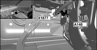
Valve block
The following valves are integrated in the valve block:
· Pressure valves of the front and rear axle
· Directional control valve
· Fail-safe valve
· Non-return valves
The valve block is located in the right front wheel arch near the A pillar. It performs the following tasks:
The oil flow to the hydraulic motors is distributed via two pressure control valves (one each for front and rear axle). The pressure at the front-suspension hydraulic motor is greater than or equal to the pressure at the rear-suspension hydraulic motor.
Measuring the actual pressure of the high-pressure oil:
There is a pressure sensor at each of the valve-block outlets for the front and rear-suspension hydraulic motors.
The direction of rotation of the two hydraulic motors is set by a shared direction valve. The position of the direction valve is detected and monitored by means of a switch position sensor (SSE).
Changeover to fail-safe mode in the event of power failure or detection of system malfunctions: The front suspension hydraulic motor is blocked sealed off. Oil can be drawn in from the tank hose through the non-return valves.
Transverse acceleration sensor
The transverse acceleration detected is the most important determining variable for the function of Dynamic Drive. The zero point of the transverse acceleration sensor can be learned by means of a diagnosis command from the Dynamic Drive control unit.
Front/rear anti-roll bar pressure sensors
The pressure sensors are located on the valve block. The zero point values of the pressure sensors are learned by means of diagnosis commands from the Dynamic Drive control unit.
Switch position sensor
The switch position sensor is located on the valve block and is used to detect the direction valve position.
Pressure control valves
The pressure control valves are located in the valve block. The valves are electrically operated. They set the active pressures for the front and rear anti-roll bars. When the vehicle is travelling in a straight line, the pressure control valves are de-energized. The oil flow to the reservoir is not restricted. When the vehicle is cornering, the valves are energized, the pressure in the hydraulic motors increases and is adjusted to the desired level.
Directional control valve
The direction valve is located in the valve block. It is electrical operated. It sets the direction of flow of the system fluid for left and right-hand bends. The position of the direction valve is monitored by means of a switch position sensor (SSE).
Fail-safe valve
The fail-safe valve is located in the valve block. It is electrically operated and when de-energized shuts off the front-suspension hydraulic motor.
Non-return valves
The non-return valves are located in the valve block. They allow replenishment of the hydraulic motors with oil thus preventing cavity formation.
Active anti-roll bars
The active anti-roll bars are vertically split in the middle. The active anti-roll bar consists of a hydraulic motor and, attached to it, the two halves of the anti-roll bar with press-fitted roller-bearing mountings. The hydraulic motor shaft and housing are each attached to one half of the anti-roll bar. In the hydraulic motor, the opposing chambers are linked. This means they each have the same pressure. A pressure port supplies two chambers with high-pressure oil while the two other chambers are connected to the return line to the reservoir. Variation of the pressure varies the force generated by the motor. That force produces torque which rotates the shaft relative to the housing. As one half of the anti-roll bar is attached to the shaft and the other to the housing, the two halves of the anti-roll bar then twist in opposite directions to one another. The stabilization torque that this creates counteracts the rolling motion. The maximum system pressure is 180 bars.
Tandem pump
The tandem pump supplies the hydraulic pressure for the Dynamic Drive and power steering circuits. The pump consists of a radial piston pump section for the Dynamic Drive system and a vane-pump section for the power steering. Dynamic Drive and the power steering share a common oil cooler and reservoir.
Oil tank
The oil reservoir has an oil filter and an oil level sensor.
Oil level sensor
The oil level sensor is mounted on the oil reservoir. If the oil level drops below the minimum mark, a signal is sent to the Dynamic Drive control unit.
Oil cooler
The oil cooler keeps the oil temperature below 120 degrees Celsius. The oil temperature is allowed to rise to a maximum of 135 degrees Celsius for short periods. The oil temperature is an important parameter for the commissioning procedure for the system as a whole. The commissioning procedure (by means of diagnosis command) must not be carried out at extreme temperatures (ambient and system temperatures).
Dynamic Drive system function
The Dynamic Drive controls two active anti-roll bars according to the transverse acceleration levels detected.
By so doing, it reduces body roll when cornering and on uneven road surfaces.
The Dynamic Drive control unit calculates from the input signals the commands that need to be sent to the hydraulic motors. The input signals are also checked for plausibility and used for system monitoring purposes.
The Dynamic Drive control unit receives the following input signals:
· Pressure in front-suspension circuit.
· Pressure in rear-suspension circuit.
· Position of direction valve.
· Transverse acceleration.
· Oil reservoir level.
The main input variable is the transverse acceleration. The following PT-CAN signals are also analyzed:
· Transverse acceleration.
· Yaw velocity.
· Vehicle road speed.
· Steering wheel angle.
This additional information improves the response time of the system.
The control unit has short circuit-proof outputs for: pressure control valve for front and rear axle, directional control valve, fail-safe valve and 5 Volt power supply for the 4 sensors (transverse acceleration, pressure sensors for front and rear suspension circuits and switch position sensor).
The valves are controlled by current modulation (pulse width modulated signal). Signals are sent to across the PT-CAN to the engine DME/DDE indicating whether additional power is required. This is the only way the power requirement can be covered, for example when idling during the commissioning procedure.
The Dynamic Drive is not active when the vehicle is stationary when all valves are de-energized. In other words, when the vehicle is stationary, the active anti-roll bars do not generate any torque. If the vehicle is leaning to one side when parked (e.g. with two wheels on the kerb or unevenly loaded), the system does not perform any adjustments despite the fact that there is a measurable lateral force. The Dynamic Drive comes into action at speeds upwards of approx. 15 km/h.
is one of the best Professional scan tools to for BMW; Autohex allows you to diagnose, code, program/flash ecus, and add new keys for BMW. For more information: BMW Scan Tool
Changing Dmaged DME in F Series