- Benz OverHead Panel
- |
- Mercedes Control Units
- |
- Mercedes Electronic
- |
- Technical Info
- |
- Car Tech Info
- |
- MicroTronik
Mercedes Benz 203 OverHead Panel Control Unit
Locations
Flow Chart Diagram
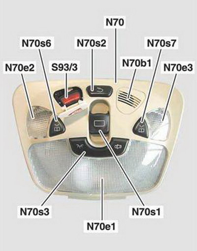
Overhead control panel
· N70 Overhead control panel control unit· N70b1 In-car temperature sensor
· N70e1 Front dome lamp
· N70e2 Left front reading lamp
· N70e3 Right front reading lamp
· N70s1 Roof switch (model 203 with code 413, 414) Tilting/sliding roof switch (model 209.3 with code 414)
· N70s2 Rear dome lamp switch
· N70s3 Dome lamp switch
· N70s6 Left front reading lamp switch
· N70s7 Right front reading lamp switch
· S93/3 SOS pushbutton switch (code 349, 359, 498)
Task
The overhead control panel control unit reads sensors and switches and controls their functions. Depending on the requests received, consumers are switched or supplied with voltage and signals are transmitted or received via CAN-B.Control
• Master control unit for interior illumination• Exit lamps
• Tilting/sliding roof (model 203.0/2, model 209.3 with code 414)
• Panoramic sliding roof and roller sun blinds (model 203.7 with code 413)
Special functions
• Windshield wiper startup suppression• OFF delay function of interior lights
• Rain closing feature of tilting/sliding roof (model 203.0/2, model 209.3 with code 414)
• Anti-throbbing function of panoramic sliding roof (model 203.7 with code 413 up to code 805)
• Dimming function of inside rearview mirror and driver-side outside mirror (code 249)
Note
The special functions are not necessarily controlled by the overhead control panel, they may just be indirectly associated with the overhead control panel.
Switching consumers
• Inside rearview mirror unit• Rear dome lamp (except 209.4) Left reading lamp (model 203.0/2) Right reading lamp (model 203.0/2)
• Roof system drive unit (model 203.0/2 with code 414, model 203.7 with code 413)
• Roller sun blind drive unit (model 203.7 with code 413)
• Tilting/sliding roof (model 209.3 with code 414)
Voltage supply
• Inside rearview mirror unit• Automatic light switch daylight sensor (light sensor) (model 203)
• Rain sensor (model 203 up to code 804 with code 345)
• Rain/light sensor (model 203 as of code 804 with code 345, model 209)
• Left interior protection transmitter and receiver (model 203.7 with code 882)
• Interior protection transmitter and receiver (model 203.0/2, 209 with code 882)
• Interior protection transmitter and receiver (slave) (model 209.4 with code 882)
• Left vanity mirror illumination (code 543)
• Right vanity mirror illumination (code 543)
• Rear dome lamp (except 209.4)
Reading integrated switches
• Rear dome lamp switch• Dome lamp switch
• Left front reading lamp switch
• Right front reading lamp switch
• Roof switch (model 203 with code 413, 414 and model 203.7 with code 413)
• Tilting/sliding roof switch (model 209.3 with code 414)
Note
The SOS pushbutton switch (code 349, 359, 498) is integrated in the overhead control panel control unit but is read discretely by the emergency call system control unit (code 359) or E-call control unit (code 349, 498).
Reading external switches
• Left soft top "locked" limit switch (model 209.4)Reading sensors
• Automatic light switch daylight sensor (light sensor) (model 203)• Rain sensor (model 203 up to code 804 with code 345)
• Rain/light sensor (model 203 as of code 804 with code 345, model 209)
• In-car temperature sensor (model 203 up to code 803 and as of code 806, model 209 as of code 806)
• Hall sensor 1 (model 203.0/2, 209.3 with code 414, model 203.7 with code 413)
• Hall sensor 2 (model 203.0/2, 209.3 with code 414 or model 203.7 with code 413)
• Roller sun blind Hall sensor 1(model 203.7 with code 413)
• Roller sun blind Hall sensor 2 (model 203.7 with code 413)
• Automatic dimming interior rearview mirror sensor, forward (code 249)
• Automatic dimming interior rearview mirror sensor, back (code 249)
• Left rear window glass breakage sensor (model 203.2 with code 882)
• Right rear window glass breakage sensor (model 203.2 with code 882)
• Rear window glass breakage sensor (model 203.2/7 with code 882)
• Left interior protection transmitter and receiver (model 203.7 with code 882)
• Interior protection transmitter and receiver (model 203.0/2, 209 with code 882)
• Interior protection transmitter and receiver (slave) (model 209.4 with code 882)
• Front SHD obstruction sensor (model 203 up to code 803)
Interface to CAN-B (via DBE)
• Automatic light switch daylight sensor (light sensor) (model 203)• Rain sensor (model 203 up to code 804 with code 345)
• Rain/light sensor (model 203 as of code 804 with code 345, model 209)
• Inside rearview mirror unit (code 249)
CAN signals
The overhead control panel control unit is a CAN-B subscriber in the overall network.Rear dome lamp switch (1)
Pressing the rear dome lamp switch (1) switches the interior illumination in the rear on or off.
Left front reading lamp switch (2) and Left front reading lamp (3)
Pressing the left front reading lamp switch (2) switches the left front reading lamp (3) in the overhead control panel on or off.
Right front reading lamp switch (4) and Right front reading lamp (5)
Pressing the right front reading lamp switch (4) switches the right front reading lamp (5) in the overhead control panel on or off.
Dome lamp switch (6) and Front dome lamp (7)
The dome lamp switch (6) is a rocker switch with 3 switch positions.
If the dome lamp switch (6) is in the center position, the automatic control for the interior illumination is activated.
The interior illumination is automatically switched on in dark conditions when:
• The vehicle is unlocked
• A door is opened
• The transmitter key is removed from the ignition lock
The interior illumination switches back off after a delay.
Pressing the dome lamp switch (6) to the right out of the center position switches off the automatic control for the interior illumination.
Pressing the dome lamp switch (6) to the left out of the center position only switches on the front dome lamp (7) in the overhead control panel.
Pressing the dome lamp switch (6) to the center position switches the front dome lamp (7) back off and reactivates the automatic control for the interior illumination.
Roof switch (8) (model 203 with code 413, 414)
Tilting/sliding roof switch (8) (model 209.3 with code 414)
Tilting/sliding roof (code 414)
Circuit 15R must be switched on to actuate the tilting/sliding roof.
Pulling the roof switch (8) or the tilting/sliding roof switch (8) towards the rear up to the actuation point and holding it there opens the tilting/sliding roof for the duration of the actuation.
The tilting/sliding roof is closed by actuating the switch in the opposite direction.
Pulling the roof switch (8) or the tilting/sliding roof switch (8) towards the rear over the actuation point and holding it there briefly automatically opens the tilting/sliding roof all the way.
The tilting/sliding roof is automatically closed by actuating the switch in the opposite direction.
Pressing the roof switch (8) or the tilting/sliding roof switch (8) upwards to the actuation point and holding it there raises the tilting/sliding roof at the rear for the duration of the actuation.
The tilting/sliding roof is lowered by actuating the switch in the opposite direction.
Pressing the roof switch (8) or the tilting/sliding roof switch (8) upwards over the actuation point and holding it there briefly automatically raises the tilting/sliding roof all the way at the rear.
The tilting/sliding roof is automatically lowered by actuating the switch in the opposite direction.
The tilting/sliding roof can be stopped in any desired position during automatic operation by briefly actuating the roof switch (8) or tilting/sliding roof switch (8) in any direction. The tilting/sliding roof stops in its current position.
Note
The cover of the tilting/sliding roof protects against solar radiation. If the tilting/sliding roof is opened, the cover is also opened at the same time. When the tilting/sliding roof is closed or raised at the rear, the cover can only be operated by hand.
Panoramic sliding roof and roller sun blind (model 203.7 with code 413)
Circuit 15R must be switched on to actuate the panoramic sliding roof and roller sun blind.
Pulling the roof switch (8) towards the rear up to the actuation point and holding it there opens the roller sun blind for the duration of the actuation.
Pulling the roof switch (8) towards the rear over the actuation point and briefly holding it there automatically opens the roller sun blind all the way.
The roller sun blind can be stopped in any desired position during automatic opening by briefly actuating the roof switch (8) in any direction. The roller sun blind stops in its current position.
The roller sun blind is always closed by pressing the roof switch (8) to the front and holding it there until the blind is fully closed.
Pulling the roof switch (8) towards the rear up to the actuation point and holding it there opens the panoramic sliding roof for the duration of the actuation.
Pulling the roof switch (8) towards the rear over the actuation point and briefly holding it there automatically opens the panoramic sliding roof all the way.
The panoramic sliding roof can be stopped in any desired position during automatic opening by briefly actuating the roof switch (8) in any direction. The panoramic sliding roof stops in its current position.
The panoramic sliding roof is always closed by pressing the roof switch (8) to the front and holding it there until the roof is fully closed.
Pressing the roof switch (8) upwards and holding it there raises the panoramic sliding roof at the rear.
Pulling the roof switch (8) downwards closes the panoramic sliding roof again.
Note
The roller sun blind can only be closed if the panoramic sliding roof is closed. It is not possible to close the roller sun blind automatically.
Note
It is not possible to close the panoramic sliding roof automatically.
SOS pushbutton switch (9) (code 349, 359, 498)
The SOS pushbutton switch (9) is covered by a safety flap labeled "SOS", which opens when pressed.
Pressing the SOS pushbutton switch (9) transmits an emergency call manually. An indicator lamp in the SOS pushbutton switch (9) flashes to indicate that an emergency call has been activated.
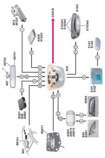
Flow Chart Diagram
· 1 Tilting/sliding roof (SHD) / panoramic sliding roof and roller sun blind OPEN/CLOSED· 2 Position of tilting/sliding roof (SHD) / panoramic sliding roof and roller sun blind
· 3 Power supply to vanity mirror illumination
· 4 Vanity mirror illumination ON/OFF
· 5 Alarm signal
· 7 Rain detected
· 8 Darkness detected
· 9 Dimming information
· 10 Reverse gear engaged or interior lights switched on
· 13 Rear dome lamp ON/OFF
· 14 Emergency call active
· 15 Emergency call signal
· 17 Power supply to rain sensor / automatic light switch daylight sensor (light sensor) / rain/light sensor
· 20 Interior protection active
· 21 Power supply to rear dome lamp
· 23 Soft top locked
· 25 Obstruction detected
· 26 Power supply to inside rearview mirror unit
· 27 Power supply to interior protection
· A26/4 Left interior protection transmitter and receiver (model 203.7 with code 882)
· A26/14 Interior protection transmitter and receiver (model 203.0/2, 209 with code 882)
· A26/15 Interior protection transmitter and receiver (slave) (model 209.4 with code 882)
· A35/8 E-call control unit (code 349, 498)
· A67 Inside rearview mirror unit
· A67h1 Automatic dimming interior rearview mirror sensor, forward (code 249)
· A67h2 Automatic dimming interior rearview mirror sensor, back (code 249)
· B61 SR [SHD] obstruction sensor unit (model 203 up to code 803)
· B61b1 Front SHD obstruction sensor (model 203 up to code 803)
· B32/1 Automatic light switch daylight sensor (light sensor) (model 203)
· B38 Rain sensor (model 203 up to code 804 with code 345)
· B38/2 Rain/light sensor (model 203 as of code 804 with code 345, model 209)
· B39 Left rear window glass breakage sensor (model 203.2 with code 882)
· B39/1 Right rear window glass breakage sensor (model 203.2 with code 882)
· B39/4 Rear window glass breakage sensor (model 203.2/7 with code 882)
· E14/1 Left vanity mirror illumination (code 543)
· E14/2 Right vanity mirror illumination (code 543)
· E15/3 Rear dome lamp (except model 209.4)
· E15/3e1 Left reading lamp (model 203.0/2)
· E15/3e2 Right reading lamp (model 203.0/2)
· E15/3e3 Dome lamp (except model 209.4)
· M12 Roof system drive unit (model 203.0/2 with code 414, model 203.7 with code 413)
· M12 Tilting/sliding roof (SHD) (model 209.3 with code 414)
· M12/5 Roller sun blind drive unit (model 203.7 with code 413)
· N70 Overhead control panel control unit
· N123/4 Emergency call system control unit (code 359)
· S84/11 Left soft top "locked" limit switch (model 209.4)
· S101 Left vanity mirror illumination switch
· S102 Right vanity mirror illumination switch
· CAN-B Controller Area Network bus class B (interior compartment)
AutoHex (Auto Diagnostic scanner) is one of the best Professional scan tools to for Mercedes Benz; Autohex Scanner can test Mercedes Benz Systems effectively and easily, with many powerful features to help you in diagnosing and testing. For more information:
Mercedes Benz Scan Tool
BMW Key Programming
Description
In this section we have some useful information about some Mercedes Benz 203 Over Head Control Panel System and it features.
Autohex II Reviews

AutoHex II
AutoHex Forum
Car Technical Information
Diagnosis and Coding