- Benz Interior CAN
- |
- Benz 204 control
- |
- Mercedes Electronic
- |
- Technical Info
- |
- Car Tech Info
- |
- MicroTronik
Mercedes Benz 204 Interior CAN Control Units
Interior CAN Components
Interior CAN Components
· 1 Electronic ignition lock control unit· 2 Left front door control unit
· 3 Right front door control unit
· 4 Left rear door control unit
· 5 Right rear door control unit
· 6 Driver seat control unit
· 7 Front passenger seat control unit
· 8 Overhead control panel control unit
· 9 Front SAM control unit with fuse and relay module
· 10 Rear SAM control unit with fuse and relay module
· 11 Tire pressure monitor control unit (USA only)
· 12 Trailer recognition control unit
· 13 PARKTRONIC control unit
· 14 KEYLESS-GO control unit
· 15 Automatic air conditioning control and operating unit
· 16 Instrument cluster
· 17 Special-purpose vehicle multifunction control unit
· 18 COMAND controller unit.
· 19 Weight Sensing System (WSS) control unit (I only)
· 20 Panoramic sliding roof control module
Chassis CAN
· 1 Electronic ignition lock control unit· 9 Front SAM control unit with fuse and relay module
· 16 Instrument cluster
· 21 ME-SFI [ME] control unit (gasoline engines)
· 22 CDI control unit (diesel engines)
· 23 Electronic Stability Program control unit
· 24 Steering column module control unit
· 25 Supplemental restraint system control unit
· 26 Left front reversible emergency tensioning retractor
· 27 Right front reversible emergency tensioning retractor
· 28 Adaptive damping system control unit
Vehicle dynamics CAN
· 23 Electronic Stability Program control unit· 29 Yaw rate, lateral and longitudinal acceleration sensor
Drive train CAN
· 21 ME-SFI [ME] control unit (gasoline engines)· 22 CDI control unit (diesel engines)
· 30 Electronic selector lever module control unit
· 31 Fully integrated transmission control controller unit
· 32 Fuel pump control unit (gasoline engines)
· 33 Electronic transmission control unit
MOST
· 18 COMAND controller unit· 34 Sound system amplifier control unit
· 35 Digital Radio Broadcasting control unit
· 36 Satellite digital audio radio (SDAR) control unit (USA only)
Telematics CAN
· 18 COMAND controller unit· 37 Audio/COMAND display
· 38 Audio/COMAND control panel
Diagnostic CAN
· 9 Front SAM control unit with fuse and relay module· 39 Emergency call system control unit (USA only)
Front end CAN
· 9 Front SAM control unit with fuse and relay module· 40 Left xenon lamp control unit
· 41 Right xenon light control unit
LIN bus
Instrument panel LIN· 9 Front SAM control unit with fuse and relay module
Wiper/inside rearview mirror LIN
· 9 Front SAM control unit with fuse and relay module
Front door LIN
· 2 Left front door control unit
· 3 Right front door control unit
Rear SAM LIN
· 10 Rear SAM control unit with fuse and relay module
On-board electrical system LIN
· 10 Rear SAM control unit with fuse and relay module
Climate control LIN
· 15 Automatic air conditioning control and operating unit
· 42 Rear automatic air conditioning operating unit
Drivetrain LIN
· 21 ME-SFI [ME] control unit (gasoline engines)
· 22 CDI control unit (diesel engines)
Steering LIN
· 24 Steering column module control unit
Note
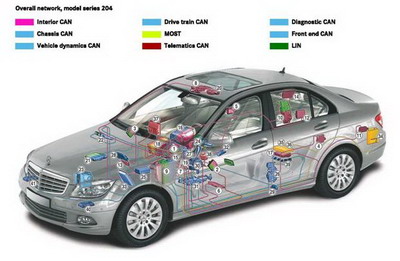
The illustration of the overall network shows a vehicle with all the available special equipment.
Electronic and electrical systems
The network architecture in model series 204 has been completely redesigned from that of the predecessor model series. The number of sub-networks in which the individual electronic control units are grouped has been significantly increased. The new architecture in model series 204 is a logical development of the electrical and electronic systems architecture of model series 221. With the focus on reducing complexity, the individual control units are grouped together in more function-related sub-networks than before in order to achieve greater reliability of the overall system coupled with lower manufacturing costs.The main features of the new network architecture include:
• Finer structuring of the CAN network
• The linking between the CAN sub-networks via several control units with integral gateway functions
• The use of numerous sub-bus systems in the form of single-wire local interconnect network (LIN) buses
Control units with integral gateway function
• Front SAM control unit with fuse and relay module with central gateway function• ME-SFI [ME] control unit (gasoline engine) CDI control unit (diesel engine)
• Special-purpose vehicle multifunction control unit
• Audio/COMAND control panel
Front SAM control unit with fuse and relay module with central gateway function
One innovation is the integration of the central gateway with the front SAM control unit with fuse and relay module in a single housing. Both control units feature separate microprocessors, each with a dedicated CAN interface.The front SAM control unit with fuse and relay module therefore has direct access to the interior CAN.
A total of six bus systems are linked together over the integrated central gateway.
These also include the diagnostic CAN, which links the diagnosis test system with the other sub-networks.
Diagnostic CAN
The diagnostic CAN is the sole diagnosis communications interface between the external diagnosis test system and the vehicle. It offers the advantages of a high data transfer rate of 500 kBit/s, compared to the 10.4 k Baud K-lines previously used, and the capability of parallel diagnosis of control units. The vehicle therefore satisfies the legal requirements for exhaust gas diagnosis that approve the diagnostic CAN as a new interface since 2003 (EU & USA) and will prohibit any other interfaces from 2008 onwards (USA).All CAN and MOST control units have diagnosis capability.
LIN components are diagnosed through their associated master control units. Each control unit has its own internal fault memory.
On-board electrical system
The supreme goal of on-board electrical system management is to assure a positive charge balance in the battery in order to guarantee that the vehicle can be started.The load state of the on-board electrical system is determined from the characteristic variables available in the vehicle, and suitable measures are initiated as and when necessary. These include, for example, specifying different charging voltages for the alternator, increasing the rpm at engine idle and, as a last resort, reducing the power of individual convenience systems.
To allow the vehicle to remain idle for long periods, the load on the battery from the quiescent current must be as low as possible. Besides optimization of the individual components, two further measures have been implemented:
· Decentralized power management and a quiescent current switch.
· Decentralized power management is integrated in all control units as a standard software module and prevents undesirable control unit activity when the vehicle is parked. The quiescent current switch is a bistable relay that is opened by the on-board electrical system management when the vehicle is idle and the run-on time has elapsed. All control units that are not required when the car is parked are disconnected from the battery, further minimizing the quiescent current demand.
Maintenance interval display (WIA) and service processor (ASSYST PLUS)
The maintenance interval display and service processor functions are integrated in the instrument cluster.The maintenance interval display computes the remaining time and remaining distance of the engine oil and triggers oil warnings.
The service processor takes the calculated values from the maintenance interval display and shows the next service date and other dates for due maintenance operation on the display in the instrument cluster. The remaining distance and remaining time are displayed.
It also shows whether a major or minor service is due and the scope of any necessary additional operations.
AutoHex (Auto Diagnostic scanner) is one of the best Professional scan tools to for Mercedes Benz; Autohex Scanner can test Mercedes Benz Systems effectively and easily, with many powerful features to help you in diagnosing and testing. For more information:
Mercedes Benz Scan Tool
Changing Dmaged DME in F Series
Description
In this section we add some useful information about some Mercedes Benz 204 Interior CAN System and it features.
Autohex II Reviews

AutoHex II
AutoHex Forum

Car Technical Information
Diagnosis and Coding