- Benz 216 Network
- |
- Benz 216 control Units
- |
- Mercedes Electronic
- |
- Technical Info
- |
- Car Tech Info
- |
- MicroTronik
Mercedes Benz 216 Networks of Control Units
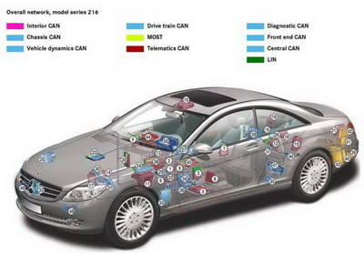
Over all Network
Vehicle power supply control
Interior CAN
· 1 Central gateway control unit· 2 EIS [EZS] control unit
· 3 Left door control unit
· 4 Right door control unit
· 5 Left front seat control unit
· 6 Right front seat control unit
· 7 Rear control unit
· 8 Left front multicontour backrest control unit
· 9 Right front multicontour backrest control unit
· 10 Overhead control panel control unit
· 11 Front SAM control unit with fuse and relay module
· 12 Rear SAM control unit with fuse and relay module
· 13 Upper control panel control unit
· 14 TPM [RDK] control unit
· 15 Multicontour seat pneumatic Pump
· 16 PTS control unit
· 17 STH control unit
· 18 TLC [HDS] control unit
· 19 Keyless Go control unit
· 20 AAC [KLA] control unit
· 21 Backup camera control unit
· 22 Weight Sensing System (WSS) control unit (USA only)
Chassis CAN
· 1 Central gateway control unit· 2 EIS [EZS] control unit
· 23 ME-SFI [ME] control unit (M273)
· 24 ME-SFI [ME] control unit (M275)
· 25 ESP control unit
· 26 Radar sensors control unit (SGR)
· 27 Steering column module
· 28 Vehicle power supply control unit
· 29 Restraint systems control unit
· 30 ABC control unit
Vehicle dynamics CAN
· 25 ESP control unit· 26 Radar sensors control unit (SGR)
· 31 Turn rate and lateral and longitudinal acceleration sensor
· 32 DTR controller unit
· 33 Night View Assist control unit
Drive train CAN
· 23 ME-SFI [ME] control unit (M273)· 24 ME-SFI [ME] control unit (M275)
· 34 Intelligent servo module for DIRECT SELECT
· 35 Fuel pump control unit
· 36 Fully integrated transmission control (VGS) control unit
· 37 ETC [EGS] control unit
MOST
· 38 COMAND controller unit· 39 SDAR control unit (USA only)
· 40 TV combination tuner (analog/digital)
· 41 Voice control system (VCS [SBS]) control unit
· 42 Universal Portable CTEL Interface (UPCI [UHI]) control unit
· 43 Amplifier for sound system
Telematics CAN
· 38 COMAND controller unit· 44 COMAND display
· 45 Front central operating unit
Diagnostic CAN
· 1 Central gateway control unit· 46 Emergency call system control unit (USA only)
Central CAN
· 1 Central gateway control unit· 38 COMAND controller unit
· 50 Instrument cluster
Door LIN
· 3 Left door control unit· 4 Right door control unit
Rear SAM LIN
· 12 Rear SAM control unit with fuse and relay module Upper control panel LIN
· 13 Upper control panel control unit Air conditioning LIN
· 20 AAC [KLA] control unit Drive train LIN
· 23 ME-SFI [ME] control unit (M273)· 24 ME-SFI [ME] control unit (M275)
Steering LIN
· 27 Steering column module Central operating unit LIN
· 45 Front central operating unitNote
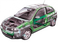
The illustration shows a vehicle with all the available special equipment
Electronic and electrical systems
The network architecture in the CL-Class has been completely redesigned from that of the predecessor model series.Compared with previous model series, the electronic of vehicle and electrical systems have been extended into new sub-networks and their tasks have been reallocated.
The central gateway control unit is responsible for coordinating the individual sub-networks (bus systems) with each other.
The sub-networks of the central gateway control unit include:
• Interior CAN
• Chassis CAN
• Front end CAN
• Central CAN
• Diagnostic CAN
In addition to the central gateway control unit, there are other control units that act as gateways:
• COMAND controller unit acts as gateway between central CAN and telematics CAN
• ME-SFI [ME] engine control unit acts as gateway between chassis CAN and drive train CAN
• ESP control unit acts as gateway between chassis CAN and vehicle dynamics CAN
MOST
The communications and information systems are networked over MOST and therefore allow synchronous data transfer.The COMAND controller unit acts as the gateway between MOST and the central CAN.
LIN bus
Certain functions are controlled via LIN bus systems.The following local interconnect network (LIN) single wire buses are used:
• Central operating unit LIN
• Door LIN
• Upper control panel LIN
• SAM LIN
• Air conditioning LIN
• Drive train LIN
• Alternator LIN
• Steering LIN
Air conditioning bus
The air conditioning bus connects the sun sensor and the multifunction sensor with the automatic air conditioning control unit.Central gateway (CGW) and diagnostic CAN
In addition to the diverse data transfer functions between the networks, the CGW also incorporates the following functions:• Maintenance interval display
• Service processor
The diagnostic CAN connects the off-board test system to the interior CAN via the CGW and to the drive train CAN via the chassis CAN.
All control units have diagnosis capability and each one has its own internal fault memory.
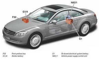
On-board electrical system management
The on-board electrical system management ensures that the power supply to all the electrical consumers and components in the vehicle is appropriate for the requirements and the situation.The on-board electrical system consists of two onboard circuits:
• The starter battery circuit with starter battery and starter.
• The supply battery circuit with on-board electrical system battery and all electrical consumers.
The two on-board circuits can be coupled whenever this is necessary for the vehicle to operate.
The on-board circuits are separate primarily in order to safeguard the starting ability of the vehicle.
For this reason consumers other than the starter are only allowed to take energy from the starter battery circuit under certain conditions.
The two on-board electrical systems are separated or coupled by means of a coupling switch in the prefuse box beside the starter battery. The on-board circuit system is coordinated by the vehicle power supply control unit.
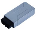
Vehicle power supply control unit
The vehicle power supply control unit is located in the right side of the trunk on the back of the rear seats above the on-board electrical system battery.Its tasks are as follows:
• Connecting the two batteries in parallel via the coupling switch
• Charging the starter battery via a transformer
• Controlling the emergency mode of the on-board electrical system
The vehicle power supply control unit contains a pyrofuse to protect the on-board electrical network line to the front prefuse box. It is tripped by crash signal 2 from the restraint systems control unit.
Starter battery
The starter battery is located on the right in the engine compartment beside the air intake of the air conditioning system.The vehicle is started exclusively via the starter battery.
Charging and jump-starting are also carried out via this battery.
The 35 Ah starter battery is not maintenance-free because AGM batteries in this power segment are not available on the market.
AutoHex (Auto Diagnostic scanner) is one of the best Professional scan tools to for Mercedes Benz; Autohex Scanner can test Mercedes Benz Systems effectively and easily, with many powerful features to help you in diagnosing and testing. For more information:
Mercedes Benz Scan Tool
Programming BMW F Series
Description
In this section we add some useful information about some Mercedes Benz 216 Network of Systems and it features.
Autohex II Reviews

AutoHex II
AutoHex Forum

Car Technical Information
Diagnosis and Coding