- Benz 221 Battery
- |
- Benz 221 Control Units
- |
- Mercedes Electronic
- |
- Technical Info
- |
- Car Tech Info
- |
- MicroTronik
Mercedes Benz 221 Battery Control Unit
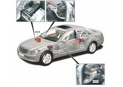
Electrical system components
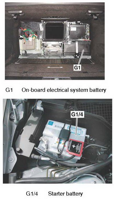
On-board electrical system battery
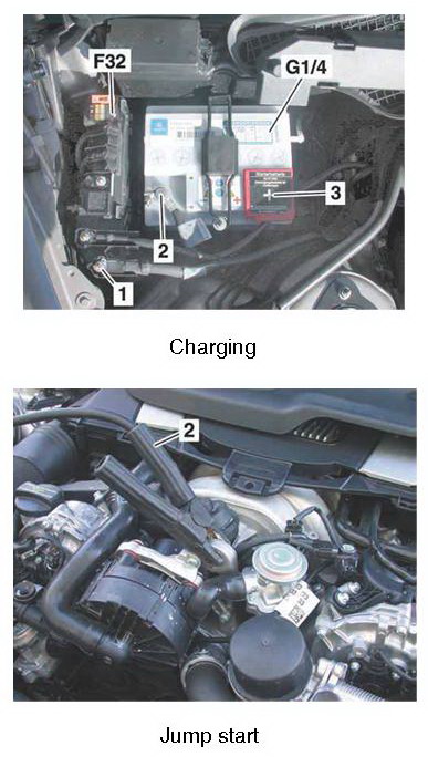
charging and jump start
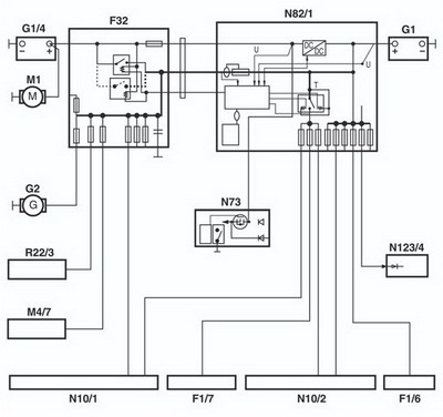
Network connection
Electrical system components
· F1/6 Right instrument panel fuse box· F1/7 Left instrument panel fuse box
· F32 Front prefuse box
· G1 On-board electrical system battery
· G1/4 Starter battery
· N10/1 Front SAM control unit with fuse and relay module
· N10/2 Rear SAM control unit with fuse and relay module
· N82/1 Vehicle power supply control unit.
Features of the on-board electrical system
Model 221 has a two-battery electrical system, consisting of a starter battery (G1/4) in the engine compartment and an on-board electrical system battery (G1) in the trunk.The task of the starter battery (G1/4) is to provide the energy required for the starting procedure and to supply the on-board electrical system when it is in emergency mode, i.e. when the on-board electrical system battery (G1) is discharged (voltage < 9 V).
The on-board electrical system battery (G1) supplies all the electrical consumers in the vehicle, even when the vehicle is idle. When diesel engines are cold started, the on-board electrical system battery (G1) is used to assist the start.
The on-board electrical system, the starter battery circuit and the on-board electrical system battery circuit are separate in order to preserve the starting ability of the vehicle.
On-board electrical system management
The on-board electrical system in model 221 is managed by the vehicle power supply control unit (N82/1). It uses the measured voltage and temperature values to evaluate the state of the battery and initiates measures to stabilize the on-board electrical system if necessary (e.g. consumer shutoff).
Fault messages in the on-board electrical system
The red fault message "Battery Symbol!" is displayed under the following conditions:• Circuit 61 not present (engine running)
• Prefuse in vehicle power supply control unit (N82/1) has blown
• Charge converter in vehicle power supply control unit (N82/1) defective
Operating principle
Normal mode• When the vehicle is opened and the transmitter key (A8/1) is inserted in the EIS [EZS] control unit (N73), the chassis CAN is woken, thereby waking the vehicle power supply control unit (N82/1). The quiescent current cutout relay (N82/1k1) is closed if it was previously opened due to the battery state (voltage < 11.8 V) or due to the timeout (t > 6h).
• During the starting procedure the on-board electrical system battery circuit and the starter battery circuit are electrically isolated from each other. The starter battery (G1/4) guarantees the starting of the engine, while the on-board electrical system battery (G1) supplies all the electrical consumers in the vehicle.
In diesel vehicles the battery coupling relay (F32k1) is closed at an engine oil temperature < -10 °C in order to provide the increased energy requirement by connecting the starter battery (G1/4) and the on-board electrical system battery (G1) in parallel. When the engine is running, the battery coupling relay (F32k1) opens again when 30 s have elapsed.
• After the engine start, the vehicle power supply control unit (N82/1) controls the charging of the starter battery (G1/4) for 1 h via the charge converter, depending on the charge level, at maximum value 25 W (corresponds to approx. 2 A depending on the state of charge), even if the vehicle has been switched off again in the meantime.
The charge converter is switched off only under the following conditions:
• At "Engine OFF" (circuit 61 "OFF") and subsequent "Ignition ON" (circuit 15).
• Voltage of on-board electrical system battery (G1) < 10.5 V (at "Ignition OFF").
• Battery coupling relay (F32k1) closed.
Emergency mode
• If the voltage of the on-board electrical system battery (G1) is < 9 V, the on-board electrical system switches to emergency mode. If the vehicle cannot be unlocked using the transmitter key (A8/1), the driver door should be opened with the manual key.
• When the transmitter key (A8/1) is inserted into the EIS [EZS] control unit (N73), a microswitch in the EIS [EZS] control unit (N73) is closed, which closes the battery coupling relay (F32k1) in the front prefuse box (F32).
In vehicles with KEYLESS GO the microswitch is closed by pressing the Keyless Go start/stop button (S2/3).
• When the battery coupling relay (F32k1) is closed, the starter battery (G1/4) and the on-board electrical system battery (G1) are connected in parallel for a period of 5 min, in order to provide sufficient energy to start the engine.
• If the transmitter key (A8/1) in the EIS [EZS] control unit (N73) is turned to "Ignition ON" (circuit 15), the coupled energy supply is only available for starting the engine for a period of 30 s.
The time is reduced from 5 min to 30 s on "Ignition ON" because many more control units have to be supplied with energy when circuit 15 is on.
If the engine has not started by the time the 30 s have elapsed, the battery coupling relay (F32k1) is opened again. Then the transmitter key (A8/1) must be inserted again in order to start the vehicle.
The battery coupling relay (F32k1) remains closed for the entire duration of the subsequent driving cycle.
Overview
On-board electrical system battery (G1)Location
The on-board electrical system battery (G1) is located behind the partition wall between the passenger compartment and the trunk on the right hand side in the trunk.
Note
The following vehicle models are equipped with a 95 Ah on-board electrical system battery (G1):
• Vehicles with stationary heater (code 228)
• Long versions (model 221.1)
• Vehicles with top protection (code Z07)
Battery
Starter battery (G1/4)
Location
The starter battery (G1/4) is located beside the air intake of the air conditioning system on the right at the rear of the engine compartment.
Charging
Note
Due to the high power requirement of model 221, only use Daimler-approved chargers with a charging current of at least 30 A.
On-board electrical system battery (G1)
The battery is charged via the front prefuse box (F32) and the starter battery (G1/4):
• Check condition of on-board electrical system battery (G1).
• Connect positive clip of charger to connection stud (1) on front prefuse box (F32).
• Connect negative clip of charger to negative terminal (2) of starter battery (G1/4).
• Charge on-board electrical system battery (G1).
Starter battery (G1/4) (external charging)
• Connect positive clip of charger to positive terminal under cover (3) of starter battery (G1/4).
• Connect negative clip of charger to negative terminal (2) of starter battery (G1/4).
• Charge starter battery (G1/4).
· 1 Connection stud
· 2 Negative terminal
· 3 Cover
· F32 Front prefuse box
· G1/4 Starter battery
Jump start
• Connect positive clip to positive terminal undercover of starter battery (G1/4).
• Connect negative clip (2) to body or engine
ground (e.g. engine block lifting lug).
• Start engine.
· 2 Negative clip
Removal/installation
NoteIn vehicles with Keyless Go (code 889), press the Keyless Go start/stop button (S2/3) repeatedly until the ignition is switched off. Remove the transmitter key (A8/1) from the vehicle and keep it outside the range of the transmitter (at least 2 m).
Before the on-board electrical system battery (G1) or the starter battery (G1/4) is disconnected from the on-board electrical system, the internal on-board electrical system functions (e.g. battery coupling relay (F32k1), charge converter) must first be terminated.
This must only be done in accordance with the "key procedure" described below:
• Engage selector lever position "P".
• Switch off all electrical consumers.
• Turn transmitter key (A8/1) in EIS [EZS] control unit (N73) to position 0.
• Turn transmitter key (A8/1) in EIS [EZS] control unit (N73) to position 2 (ignition "ON") and wait 30 s.
• Turn transmitter key (A8/1) in EIS [EZS] control unit (N73) to position 0 and leave it in the EIS [EZS] control unit (N73).
Network connection:
· F1/6 Right instrument panel fuse box· F1/7 Left instrument panel fuse box
· F32 Front prefuse box
· G1 On-board electrical system battery
· G1/4 Starter battery
· G2 Alternator
· M1 Starter
· M4/7 Engine and air conditioning electric suction fan with integrated control
· N10/1 Front SAM control unit with fuse and relay module
· N10/2 Rear SAM control unit with fuse and relay module
· N73 EIS [EZS] control unit
· N123/4 Emergency call system control unit
· N82/1 Vehicle power supply control unit
· R22/3 PTC heater booster
AutoHex (Auto Diagnostic scanner) is one of the best Professional scan tools to for Mercedes Benz; Autohex Scanner can test Mercedes Benz Systems effectively and easily, with many powerful features to help you in diagnosing and testing. For more information:
Mercedes Benz Scan Tool
BMW ECU Programming
Description
In this section we add some useful information about some Mercedes Benz 221 Battery System and it features.
Autohex II Reviews

AutoHex II
AutoHex Forum

Car Technical Information
Diagnosis and Coding