Injectors of the Vehicle
injection system and control
Injectors and spray types
1. Injector Overview
Injector is an injection nozzle with solenoid that is controlled by ECM.Using intake air quantity and engine rpm, ECM calculates basic fuel injection time, and calculates corrective fuel injection period time on the basis of engine coolant temperature, feedback signal from oxygen sensor during close-loop-control, driving conditions including acceleration, and deceleration, and battery charging status, in order to control injector by means of pulse signal is constant, and injecting pressure is controlled to be constant. Then fuel injection quantity will rely on the length of time-injecting cycle in which solenoid will be magnetized and hold needle valve open, say pulse width modulation (PWM) transmitted from ECM.
The longer injection cycle means (longer the pulse width) and the more the injected fuel from injector.
Injection quantity is decided in accordance with injector operating time as calculated by ECM on the basis of intake air quantity, and general driving condition. Basically two types of system are used as follows:
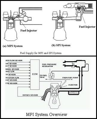
- MPI (Multi-Point Injection).
- SPI (Single-Point Injection).
- As to SPI system, gas fuel is injected by one injector located at top center of throttle valve. Distribution of air/fuel mixture that will be delivered to each cylinder will be achieved by intake manifold. It is not commonly used for the systems of these days because of the bad distribution.
- As to MPI system, each cylinder requires one injector, which is installed intake manifold and injects toward the intake valve of each cylinder. Fuel supply to each injector relies on fuel rail.
Using a number of sensors, MPI system continuously measures engine operating condition, and calculates proper fuel quantity relying on pre-set method by ECM, so as to provide optimal fuel quantity. Therefore engine output, engine torque, emission, fuel mileage and drivability may be provided as per the requirement of the engine designer.
The calculated fuel quantity will be directly injected toward intake valve of the engine, and then only air will pass intake manifold, increasing design flexibility.
MPI System has advantages over carburetor that had been widely used until end of 1989, as follows:
(1) Precise fuel quantity calculation under any stable conditions and temporary condition (acceleration enrichment, warm-up enrichment, etc)
(2) No fuel stuck on inner wall of intake manifold during the fuel transfer intake manifold.
(3) Precise fuel distribution at pre-load.
(4) Design flexibility for intake manifold.
(5) Simple and effective use of Lambda closed loop control.
(6) Low emission.
(7) Easier diagnosis and repair.
The above advantages may provide improved variables of engine and subsequently high output. However poor micro-measurement in idling may be a disadvantage.
2) SPI System
SPI system was first introduced in 1979 by GM and Ford, and become successful by Chrysler in USA and by Mitsubishi in Japan. Besides Bendix, Bosch, Holley and Hitachi also announced their own specific systems.
SPI system uses one injector (in case of two barrel intake manifold for V6 or V8 engines, two injectors) to inject fuel through top of throttle plate. This type of injection requires injecting fuel through the gap between throttle plate and intake manifold wall, and consequently cone type configuration.
SPI has many of the same advantages as MPI. To say, SPI system measures fuel quantity on the basis of injector opening time or injection frequency, to allow easier computer-control and to provide precise fuel measurement. In addition, the system provides advantageous installation, closed loop control, easier diagnosis & repair, and good micro-measurement characteristics in idling with one point injection type.
SPI system however has some disadvantages as carburetor. To say, there is uneven fuel distribution among cylinders, and fuel supply may be delayed in response to air supply. Those systems with increased active range of injector and low fuel pressure during engine warming-up may provide low performance. SPI system is superior to a carburetor in performance and emission control.
No. 1 is the terminal that receivers injecting signal from ECM and is controlled by power TR operation in ECM. No. 2 is the terminal receiving power from control relay.
2. Configuration and Operation Principle
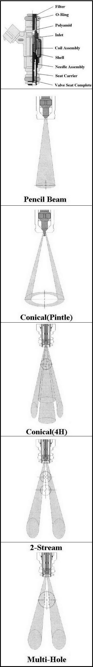
1) ConfigurationInjector consists of numerous parts. However the parts may be classified into three groups:
(1) Coil assembly generates force using supplied power.
(2) Magnetic Circuit acts as path of generated magnetism.
(3) Valve group controls fuel quantity.
- Coil assembly includes coil wire, Bobbin and terminals.
- Magnetic circuit includes inlet tube, shell, and armature and seat carrier.
- Valve group that controls fuel quantity includes needle assembly (Bail, Needle Shaft and Armature) and valve seat complete (Valve Seat and Spray Hole Plate).
MPI systems may be classified into two types by fuel intake line into injector. Bottom feed types take in fuel at bottom or side and top feed types take in fuel at top. Both types use spray hole to inject measured fuel.
Fuel flows through filter part located at inlet to fuel measuring part. Fuel measurement will be performed at valve seat part located to spray hole. When pulse is not adjacent delivered to coil assembly, say power is not supplied, spring force and system pressure will press needle toward valve seat part, in order to prevent fuel injection by injector and leakage.
When pulse is provided to coil assembly and create magnetic field, the magnetic force will pull needle from valve seat making space for fuel passage between valve seat and needle. Fuel then will pass through the space and thereafter spray hole to be injected outside. When coil does not receive pulse, then needle will return to close position by spring tension.
3. The Basic Requirements of Injector and Spray Characteristics.
1) Basic RequirementInjector has basic requirement that shall be ensured under all operating conditions such as short and long injection times, cold start, hot start, etc, in the sense of flow characteristics as well as endurance characteristics. Among the six items listed below, first five items are basic characteristics and item 6 are endurance characteristics.
(1) Precise fuel flow-rate
(2) Good linearity at low flow rate and wide active range.
(3) Good spray characteristic.
(4) No leakage.
(5) Low noise.
(6) Endurance performance.
2) Spray Characteristics:
Spray characteristics may be analyzed by sprayed particulate formation, spraying pattern, and spray distribution characteristics. Each is described below:
(1) Pencil Beam
Pencil Beam is the fuel particulate pattern injected by a single hole type injector. Basically this particulate pattern is used at limited conditions that require particularly decided fuel particulate and spraying pattern.
(2) Conical Spray (Pintle Type Injector)
Precisely machined conical shape at end of needle valve located at fuel outlet, can respond to different spraying angles required by engine. In addition sharp outlet edge at tip of the cone ensures better fuel particulate.
(3) Conical Spray (Four-Hole Injector)
A four-hole injector has advantages over a Pintle type injector in relation with fuel particulate and spraying angle. Each thin spray will be formed by the four holes installed on orifice plate at specific angle against axial direction of the injector. Each spray will form specific spray angle and provide better particulate effect, used together with protective sleeve.
(4) Two-Spray Injector
Engines with two inlets per cylinder use this injector. The center lines of sprays shall orient toward intake valves. Then the engine requires injectors that generate two separate sprays with different spraying angles.
(5) Multi-Hole Injector
Fine holes at orifice plate enable to generate better particulate effect of sprayed fuel, and different angles of holes prevent spray particles from confinement that may occur by reduced momentum of fuel spray.
3) Checking of injector
Injector shall be checked for operation noise, the resistance of injector, fuel injection rate, fuel spray pattern (spray angle, rear trace, etc). However it is not easy to directly check fuel injecting rate or fuel spray pattern on an actual car.
Check connectors for connected status, and wires for disconnection and short.
Check if correct injectors are installed. Injector operation noise may be checked using a stethoscope in general.
If hot engine is hard to start up, and then check fuel pressure and injector leakage.
If engine cranking fails to operate injectors, check ECM power supply circuit and grounding circuit, control relay, crank angle sensor or No1 cylinder TDC sensor for defects.
When shutting down fuel injection of injectors one by one during idling, if a cylinder is not proved to change its idling status, check the cylinder for injector harness, ignition plugs high voltage cable, compression pressure, etc.
In addition if injector harness and each part are checked to be normal and how ever injector operation time is outside the specified value, then check whether there are imperfect combustion in cylinder (defective ignition plugs ignition coils, compression pressure, etc) and whether EGR valves operate normally.
Let us look at the each checking methods one by one as for the resistance check, measure the resistance directly after removing the injector connector. Then, the inner coil condition of the injector can be checked.
To check the injector operating sound, contact the stethoscope or driver to the injector while the engine is running. The operation sound of the plunger or needle valve can be checked. To check the injector operation with the test lamp, connect the end of the test lamp to the positive terminal of the battery, and connect the other end to the terminal at the ECM side of the injector. Then crank or idle the engine to check whether the lamp blinks.
Through this test, we can check whether the ECM controls the injector or there is any wiring trouble.
To check with the waveform, we can check the waveform at the ECM side wire. In injector waveform, the voltage before and after injection operation should be equal to the battery voltage. If not, there should be a problem in the power supply system from the battery positive terminal to the injector. Besides, voltage should be close to 0 volt. If not, there should be problem with the ECM and wirings from injector to ECM ground.
4) Fuel injection Pattern Analysis
Injector drives are divided into pick and hold type injector and voltage drive type injector. In addition injectors may be classified into low resistance injectors and high resistance injectors depending on resistance level of the injectors. Voltage drive injectors include low resistance injectors and high resistance injectors, and especially low resistance type has coil resistance of approx. 0.6~3 Ohms, and uses an external resistance together. It is intended to increase response and endurance of injectors, and achieved by decreasing number of winding times of solenoids.
By reducing number of windings of solenoid coils, current is increased and injectors have better operation characteristics. Then excessive current may flow through solenoids to damage coil or decrease endurance. Therefore an external resistance is used to avoid mentioned damages. High resistance injectors have resistance of 12 ~17 Ohms to increase solenoid coil resistance for limiting current. This type of voltage drive has simpler circuit configuration, but increase impedance, so that current at injector may be reduced to lower sucking force of injector, and resultantly provide relatively inferior dynamic range characteristics.
Injectors have peak and hold circuit by ECM, and when injecting signal is on, current delivered to injector will change. At initial stage of injector operation, high current flows to increase magnetic force and decrease inertia of solenoid to enable initial operation, and use low current after needle valve opens. Peak and hold type has complicated circuit configuration, but has low circuit impedance for superior dynamic range characteristics of injector.
In addition Soho circuit in injector drive circuit protects power transistor from reverse-electromotive force generated at solenoid coil when injection signal is off, and eliminates arc in order to reduce valve close time of injector.
You can check the actuator actual value and status and activate it when it is possible by AutoHex automotive Diagnostic Scanner under the supported car brand and according to engine type.
Programming BMW F Series
Description
Injector is an injection nozzle with solenoid that is controlled by ECM.
Using intake air quantity and engine rpm, ECM calculates basic fuel injection time, and calculates corrective fuel injection period time on the basis of engine coolant temp, feed back signal from oxygen sensor during close-loop-control,
Autohex II Reviews

AutoHex II
AutoHex Forum