- Air Flow Meters
- |
- Engine Sensors
- |
- Fuel Injection
- |
- Repair Basics
- |
- Technical Info
- |
- Car Tech Info
- |
- MicroTronik
Air Flow Meter Sensors
MAF sensor
Hot Wire MAF Sensor
Ford Hot Wire MAF Sensor
MAP Sensor
Moving Vane
This type of Air Flow Meter is probably the most popular version and has been used on systems such as Bosch L, LE, LE3 and Motronic, Ford EEC IV. Several Japanese manufacturers have also based their systems around this tried and tested unit. The air vane meter adopts the principle of the airflow flowing into the engine and passing through the metering unit via a spring loaded flap, which in turn moves in proportion to the amount of air entering the engine. The movement air vane is recorded by a (wiper arm) moving across a carbon track, whose output is reported back to the Electronic Control Module (ECM) and gives the correct amount of fuel for the air recorded.The voltage output from the internal track should be proportional to flap movement. The waveform should show approximately 1.0 volt when the engine is at idle, but this voltage will rise as the engine is accelerated and will produce an initial peak.
This peak is due to the natural inertia of the air vane and drops momentarily before the voltage is seen to rise again to a peak of approximately 4.0 to 4.5 volts.
This voltage however depends on how hard the engine is accelerated, so a lower voltage is not necessarily a fault within the AFM. On deceleration the voltage drops sharply as the wiper arm, in contact with the carbon track, returns back to the idle position.
This voltage may in some cases (dip) below the initial voltage before returning to idle voltage. A gradual drop will be seen on an engine fitted with an idle speed control valve, as this will slowly return the engine back to base idle as an anti-stall characteristic.
A time base of approximately 2.5 seconds or more is used; this enables the operator to view the movement of the AFM on one screen, from idle, through acceleration and back to idle again. The waveform should be clean with no (drop-out) in the voltage, as this indicates a lack of electrical continuity.
The AFM also has an internal compensation chamber that stabilizes the movement of the flap and avoids erratic movement from induction pulses. The co-mixture content adjustment, when applicable, is via an internal air by-pass or a potentiometer, depending on the version.
The AFM can have a varying number of electrical connections, from four to seven.
This particular 12 volt supplied Air Flow Meter (AFM) was used on early electronic injection systems and has the same operational qualities as the later 5 volt versions. The voltage should be seen to rise as the air vane is moved with no breaks or loss of continuity.
Its shown clearly that just as the vane moves, contact is lost, with the same fault occurring again as the throttle is released and the engine returns to idle.
An AFM with this particular output would produce (flat-spots) or (hesitations) when driven. As the carbon tile has sustained damage the only way to rectify this problem is to change the unit for a new one. Removal of the plastic cover will invariably show the white plastic of the tile clearly visible through the carbon track. However, this may only become apparent when the track is cleaned with a contact cleaning solvent.
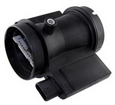
Mass Air Flow (MAF) Sensor
The Mass Air Flow Sensor is probably the best way to measure the amount of air an engine takes in (engine load). This sensor not only measures the volume of air but also compensates for its density as well. Ford, GM, and many imports are using engine control systems based around this sensor.There are two common designs of MAF sensors used in the vehicles of today. One produces a variable voltage output (analog) and the other produces a frequency output (digital). In either case their operation is similar. Both outputs can be measured by a scanner or a digital volt/ohm meter (DVOM) that can measure frequency.
Both designs work on the (hot wire) principle. Here is how they work. A constant voltage is applied to the heated film or heated wire. This film or wire is positioned in the air stream or in an air flow sampling channel and is heated by the electrical current that the voltage produces. As air flows across it, it cools down. The heated wire or film is a positive temperature coefficient (PTC) resistor. This means that its resistance drops when its temperature drops. The drop in resistance allows more current to flow through it in order to maintain the programmed temperature. This current is changed to a frequency or a voltage which is sent to the computer and interpreted as air flow. Adjustments for air temperature and humidity are taken into consideration since they also affect the temperature of the heated wire or film.
Humidity always affects the density of air since humid air is denser than dry air. No other compensation is therefore needed for this factor. Air temperature affects density since colder air is denser than warmer air. Many systems use an air temperature sensor to compensate for this factor since similar amounts of air can enter an engine at different temperatures. Some MAF sensors use an internal (cold) wire to send ambient temperature information to the computer. Some use an intake air temperature sensor in the manifold or the intake piping. This sensor is almost always NTC in design (negative temperature coefficient). That is, its resistance goes up as air temperature goes down. This (thermistor) works just like a coolant temperature sensor and usually has identical resistance to temperature values. By the way, these values are very different from manufacturer to manufacturer and are available in most repair manuals. They are also programmed into scanner software.
Now, as we discussed, the MAF sensor sends either a variable voltage or a changing frequency to the computer. The computer is programmed to accept this information when the car is running in any mode. For example, idle rpm will send a low voltage or low frequency and a high revving engine will send a high voltage or high frequency to the computer along a specific wire (the MAF signal wire). If the signal is not present when it should be and within a programmed parameter, say high voltage at high throttle opening, the computer will set a code.
So, there are several things to consider whenever there is a code which points to the MAF sensor as the problem:
1. Derive the code(s) by the recommended method of the manufacturer.
2. Look up the code(s) in a service manual.
3. Read the explanation(s) carefully!
4. A code that indicates an out of range signal is often an indication that another sensor, like the throttle position sensor or the rpm input signal is contradicting the MAF signal. The cause might be the other sensor or signal being out of adjustment or faulty.
5. A code that indicates a low MAF signal may be set by various problems. These include the following:
1. A bad MAF sensor (internal fault)
2. Any wire on the MAF sensor circuit including:
A. the 12 volt feed wire which connects the MAF to the battery through the ignition switch or through a relay as in many GM applications
B. the MAF ground wire
C. the output wire
D. the MAF or computer connectors
E. the computer
Hot Wire / Film
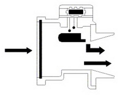
The hot wire air flow meter is, in many ways, advantageous over the conventional air vane meter as it offers very little resistance to the flow of incoming air. The mass air flow is measured by the cooling effect on a heated wire that is suspended in the air passage, and it is the cooling effect of the air flow on the wire that signals to the Electronic Control Module (ECM) the quantity of incoming air.The AFM is once again located between the air filter and the throttle butterfly. Inside the component are two wires, one of which is used to sense the temperature of the incoming air and the other heated to a high temperature (approximately 120 °C) by passing a small current through it. As the air flows across the heated wire, it has a cooling effect on it causing a resistance drop; a small circuit inside the component increases the current passing through the wire to maintain the temperature, and it is the recognition of this current that signals to the ECM the mass air flow. The current supplied to the heated wire alters proportionately to the airflow.
Any wire that is constantly heated forms an oxide coating. To clean the wire after each journey, a current is passed through the wire heating it to approximately 1000 °C, burning off any build up, and ensuring a clean wire for the next time the vehicle is started.
The operating principles for the (hot film) version are almost the same but with greater reliability, due to the absence of the heated wire that is now replaced with a solid-state component.
MAP Sensors
The Manifold Absolute Pressure (MAP) sensor is employed to measure the vacuum in the inlet manifold. It is this output that when sent back to the engine management system can determine either the fuelling or the amount of vacuum (or light load) advance.The sensor is a three wire device which has:
A 5 volt supply voltage
An earth connection
A varying analogue output
A vacuum connection to the inlet manifold
This particular component can be either an integral part of the electronic control module or an individual component. The output from the external sensor will show a rise and fall voltage depending upon the vacuum seen.
When the engine is stationary or the throttle is wide open, zero vacuum will be recorded and a voltage approaching 5 volts will be seen; as a vacuum is applied the voltage will reduce.
All voltages are similar between different manufacturers and a lower than anticipated voltage will produce a loss of power due to fuel starvation. Conversely a higher voltage will cause over fuelling and could eventually result in the failure of the catalytic converter if subjected to long term abuse. This high voltage could result from any number of problems but may be as simple as a split vacuum hose or incorrectly adjusted tappet clearances. The voltage from an integral MAP sensor can only be evaluated when a Fault Code Reader (FCR) is used due to the lack of access to the output voltage.
AutoHex (Auto Diagnostic scanner) is one of the best Professional scan tools to for Cars; Autohex Scanner can test the Systems of the Car effectively and easily, with many powerful features to help you in diagnosing and testing.
Kia/Hyundai Key Teaching and PIN Code Calculation
Description
The following section give some details about Air Flow Meter Sensors input to the ECM of the vehicle that contribute towards the desired injector duration
Autohex II Reviews

AutoHex II
AutoHex Forum