- The Hall-Effect Sensor
- |
- Engine Sensors
- |
- Fuel Injection
- |
- Repair Basics
- |
- Technical Info
- |
- Car Tech Info
- |
- MicroTronik
The Hall-Effect Sensor
General Motors
Ford
Chrysler
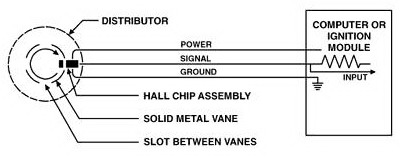
Typical Hall-Sensor Circuit
The Hall-Effect sensor is a very accurate way for a computer to (see) the exact position or measure the speed of a spinning shaft. Most designs utilize a shutter which passes through an opening in the sensor. The opening has a magnetic field passing across from a permanent magnet to the electronic switch. When the shutter passes through the magnetic field,
it is interrupted and a change in voltage is sensed by the computer. With the shutter in the opening, the voltage falls to near zero. With the shutter out of the opening, the voltage rises to the specified voltage level. This voltage is usually equal to battery voltage on GM, Ford and many Chrysler engines. However, on Chrysler 3.3L, 3.8L and 3.5L engines, the EC sends out an 8 volt power supply and receives a 5 volt-0 volt signal back on the sensor output wire. Some Hall Sensors use a moving magnet attached to a timing chain sprocket (GM) or notches in the flex plate (Chrysler) to generate a signal.
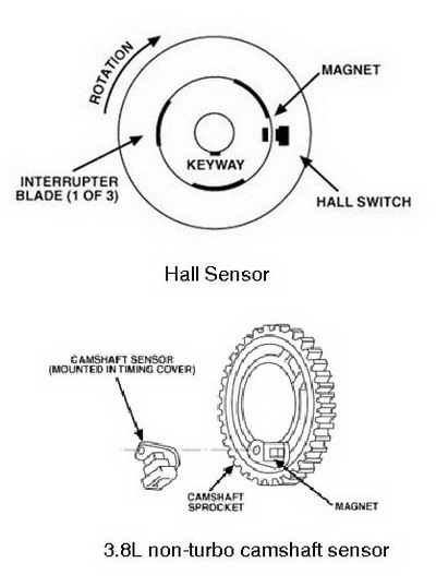
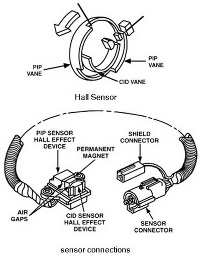
General Motors, Ford and Chrysler all have engines that utilize dual Hall Sensors in one assembly. Chrysler Turbos have two separate sensors mounted to the distributor base with their own separate three wire connectors. GM and Ford engines utilize dual Hall Sensors in one assembly with one 4 wire connector. Both of these sensors share the 12 volt power wire and the ground. The other two wires are the 12 volt-0 volt output wires for the two sensors. GM also uses separate crank and cam sensors in conjunction with Distributorless Ignition and Sequential Fuel Injection timing.
Ford vehicles primarily use Hall-Effect sensors to signal the Thick Film Ignition (TFI) module. This is called the Profile Ignition Pick-up (PIP) signal and is relayed to the Electronic Control Assembly (ECA). The Ford DIS system utilizes a second sensor (in the same assembly) to identify number one cylinder. This is called the Cylinder Identification signal (CID).
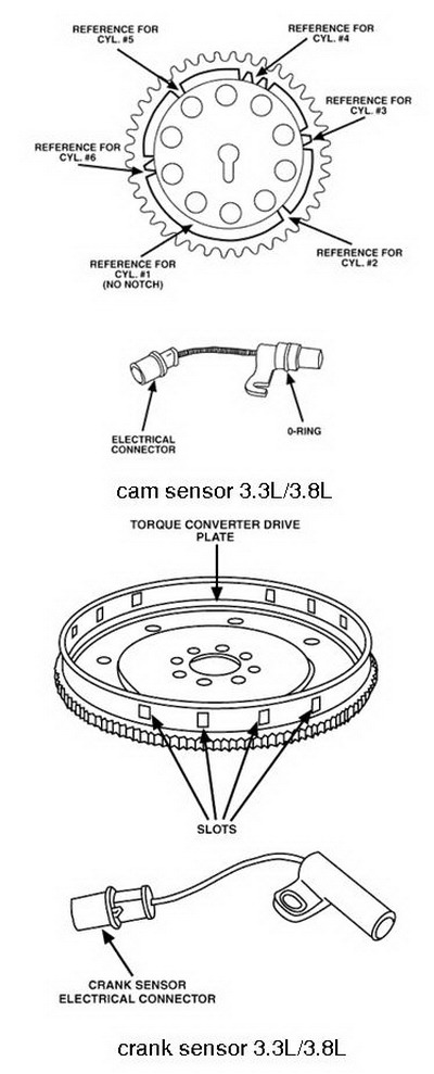
Chrysler began using Hall Sensors with the introduction of the Omni/Horizon 1.7L engine back in 1978 and continued using it in later models. The sensor was located in the distributor and the shutter was part of the rotor assembly. This type worked off of a 12 volt circuit and sent the signal to an Electronic Ignition Module or to a Spark Control Computer. Later, during the 80s Chrysler introduced the DIS system and the Hall Sensors changed locations and design. A crank sensor, located in the bell housing, reads engine speed as 3 groups of 4 notches pass by the sensor. The cam sensor, located in the front cover reads cam position as notches on the cam sprocket pass by. These Hall Sensors work from an 8 volt power supply and the output is a 5 volt-0 volt signal to the Engine Controller (EC).
All Hall-Effect sensors use three wires to do the job. One wire carries the power voltage and a second wire supplies the sensor ground. Both are supplied by the ignition module or computer. The third wire is the (toggle). This wire is the output of the sensor to the computer. The voltage rises, usually to power voltage, and falls to near zero with the movement of the shutter as explained earlier. The signal is a square wave and therefore needs no analog to digital conversion to be read by the computer. The computer measures the time between the pulses and calculates RPM for fuel and timing requirements.
Testing a Hall-Effect sensor is simple if you understand them and have a digital volt-ohm meter or a lab scope. The most difficult part of a test would be accessing the wires of the sensor. All technicians should acquire a good set of jumper wires in order to probe the Hall Sensor connectors without damaging the circuit.
Typical Hall-Sensor Circuit
To function correctly, a Hall-Effect sensor must have power voltage and ground applied to it. If the power, ground, or signal wire, are open, the sensor can not operate. A short to ground on either the power wire or the signal wire also eliminates the RPM signal.AutoHex (Auto Diagnostic scanner) is one of the best Professional scan tools to for Cars; Autohex Scanner can test the Systems of the Car effectively and easily, with many powerful features to help you in diagnosing and testing.
Programming BMW F Series
Description
The following section give some details about The Hall-Effect Sensor input to the ECM of the vehicle that contribute towards the desired injector duration.
Autohex II Reviews

AutoHex II
AutoHex Forum