- Air Flow Sensor
- |
- Sensors
- |
- Repair Basics
- |
- Technical Info
- |
- Car Tech Info
- |
- MicroTronik
Air Flow Sensor
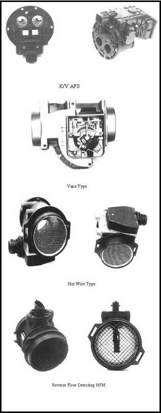
Air Flow Sensor types
Air Flow Sensor Function
1) Function
In order to achieve optimum idle mileage control for an electronically controlled fuel injection system, accurate measurement of intake air is required. AFS (air flow sensor) measures intake rate of air that is filtered by air cleaner, and one of the most important components of EMS.Therefore AFS shall have:
- Accurate response characteristic over wide air rate range.
- Immediate response characteristic against rapid change of air flow rate.
- Easy processing of signal.
- Direct Detecting Type.
(1) Air Volume Detecting Type.
A. K/V (Karman Vortex) Type.- Ultrasonic Type.
- Mirror Type.
- Pressure Sensing Type.
(2) Air mass Detecting Type.
A. Hot Wire Type.
B. Hot File Type. - Indirect Detecting Type.
A. Speed Density Type.
B. Throttle Speed Type.
2) Configuration and Operation Principle
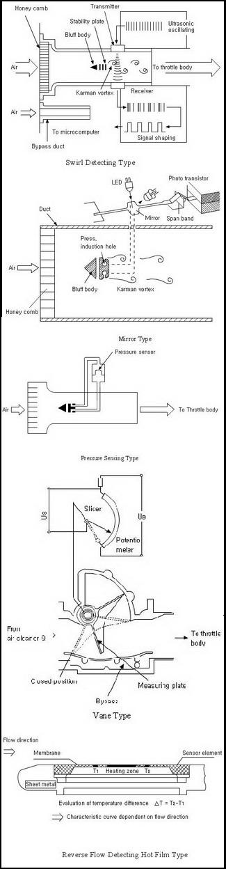
(1) K/V TypeA - Configuration of Ultrasonic Type
- Main Route and By-pass Route
Main route maintains air flow to generate constant swirl using a triangular prism, and consists of swirling prism and plane plate. By-pass route controls air flow rate as required by engine by increasing/ decreasing the route section area, not by changing main route shape.
When air flows through main route, ultrasonic wave sent from ultrasonic transmitter, will pass through swirl to the receiver. Then the frequency of ultrasonic wave will be modulated periodically by the generated swirl.
Control circuit detects potential difference of ultrasonic wave that passed through K / V, and generates electrical pulse signal that is proportional to air flow speed, out of the wave form passed through filter. The circuit consists of hybrid IC.
K / V AFS measures air temperature at AFS inlet in order to compensate intake air density, using air volume detecting type. B - Measuring Principle (Swirl Detecting Type)
When installing triangular prism (swirling pillar) in fluid flow using K / V phenomenon, asymmetrical and regular swirl occurs behind the prism. The sensor detects the swirl using ultrasonic wave and transform it to electrical pulse signal.
C - Mirror Type & Pressure Sensing Type
This type of AFS is using K / V phenomenon that induce pressure varying by swirls generated alternatively at both ends of swirling pillar, through pressure inlet opening, and then detect the pressure variation through the twisting vibration of the mirror (mirror type) or pressure sensor(pressure sensing type), and finally convert it to electric signals.
Mirror type relies on the principle that electrical signal will be generated when light emitted from LED that is located at the top side of the mirror is reflected by mirror and then emitted to photo transistor. When mirror vibrates by pressure change, light intensity will change according to reflecting angle, then it will be detected as current variation that then will be converted to pulse signal. Therefore we can get electric pulse signal corresponding to swirl occurrence.
(2) Vane Type
Movable vane type uses the principle that movable angle of the vane will correspond to air intake, rate when intake air flows through the route and movable kinetic force of the vane and return recovery force of the spring are stabilized with each other. The opening angle is detected by potentiometer that is linked to movable vane.
- Configuration
Compensation plate and dampening chamber stabilizes vane motion against rapid change of air intake rate and air pulsation. Idle-mixture adjusting screw is installed at by-pass route, and used to adjust the feature at low air rate. The screw adjusts idling mileage that varies by each engine and system, within specified objective range by adjusting by-pass route area and consequently changing AFS output. - Measuring Principle
Movable vane type AFS relies on the principle that measuring plate (vane) is pushed open by pressure gap generated by flow of air sucked into engine. On turning axis of vane is located return spring of spiral shape. Vane stops at the position where air flow force to open vane and recovery force of return spring are balanced. Potentiometer detects the position to obtain voltage value corresponding to intake air rate.
- Configuration
The sensor consists of air temperature compensation resistance that detects intake air temperature, circuit part that generates heat corresponding to heat generation, control circuit part for measurement, and housing. - Measuring Principle
When heating object is placed in the air the object is cooled by emitting heat toward air, and if there is higher air flow around the object heat loss will increase by air. Hot wire type sensors use the said phenomenon of heat transfer between a hot object and air. This type is detecting air mass and not affected by air density variation. Therefore ECU in principle is not required to compensate against temperature or pressure.
- Configuration
Hot film type depends on the same principle of heat transfer as hot wire type, but has some improvement of demerits from hot wire type as follows:- Simplified by-pass design by reducing sensor wire length. Better connection with throttle body.
- Cost saving.
- Eliminates wire dirt build-up (foreign material build-up on sensing resistance surface).
- Faster response.
- Measuring Principle
In principle the measurement basically relies on heat transfer system.
Sensor resistance (Rs) that constitute Wheatstone bridge circuit is heated by rear-side heating resistance (Rh) to be constantly 170 Degree C higher than ambient air temperature. If air flow increases, sensing temperature of the resistance will decrease and the resistance value will drop. Then Wheatstone bridge circuit will be unbalanced to generate heating current, and then heated heating resistance will raise sensing temperature of the resistance and resistance value to achieve balance. The voltage value generated by heating resistance and heating current will be proportional to air flow rate and consequently possible to measure. Air temperature compensation resistance (Rt) is designed to compensate resistance variation of sensor output characteristic value by (Rh) and (Rs) variation depending on ambient air temperature.
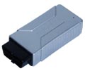
- Configuration
This type HFM has plug-in sensor integrated at the same air route part as air cleaner housing, on used as plug-in sensor module integrated onto cylinder housing. In addition various size cylinder housings are designed depending on required air flow rate for combustion engines. Then this type HFM may be said to have basically same configuration with conventional HFM type. However some difference exists for sensor element that senses air flow rate and basic measuring principle.
Sensor element consists of thin silicon diaphragm manufactured using MEMS (micro electro mechanical system) technology, and heating resistance and a number of temperature sensors which are installed on the diaphragm.
The signal of the Sensor processing circuit is configured on ceramic board (hybrid IC) located inside plug-in sensor housing, and includes sensor dement and Au-wire bonding. In addition EPROM type is used to adjust output characteristic against air flow value, and the circuit is filled with Si-Gel to protect the circuit. HFM5f includes separate intake air temperature sensor installed on plug in sensor housing. - Measuring Principle
The thin diaphragm integrated on sensor element is made by etching technology. On diaphragm, heating resistance is located at center, and temperature sensors T1 & T2 each at front and rear side of heating zone at air flowing direction. The two sensors will have same temperature when there is no air flow. However when air flows; T1 sensor located in front of heating zone will be cooled by heat recirculation. On the contrary T2 sensor located at rear of heating zone will maintain almost same temperature by air heated through heating zone. Therefore the two sensors will indicate temperature gap by air flow rate through the route, and the temperature gap will depend on air flow rate that will pass through sensor element. If reverse air flow occurs through sensor element, the temperature between T1 and T2 will be reversed, as well. Therefore detecting the temperature gap will enable detecting possible reverse flow.
- Pressure Sensor Pressure Sensor detects intake pressure variation of the manifold as voltage variation, and connected with surge tank via rubber hose or directly attached at surge tank. Pressure sensor is constituted of pressure conversion element and circuit part that processes conversion output signal of the element. The output of the sensor is proportional to intake vacuum pressure of the manifold.
- Intake Air Temperature Sensor. Intake air temperature sensor detects engine intake air temperature. In case of direct measurement type, the sensor is installed at air intake hose or AFS. In case of speed density type the sensor may be installed at surge tank in order to sense intake air temperature at pressure induction part. (MAP with IAT sensor).
This type detects air intake rate by estimating air intake quantity into engine per cycle based on throttle opening angle and engine rpm, and calculate gasoline injection rate. However air intake rate and the two measurements have complicated functional correlation and consequently detecting air quantity is not easy. Therefore currently no vehicle of this type is at market.
Only some systems that take other type of AFS are using this type as backup mode in case of AFS failure.
3) Failure Symptoms
- Cranking is possible but engine start-up is poor.
- Engine running is unstable during idling.
- Engine goes off during idling or running.
- Poor acceleration during car-running.
- If air rate sensor output value is incorrect, shock may occur during shift of an auto transmission, and in case of complete failure delayed shift may occur.
Changing Dmaged DME in F Series
Description
Air Flow Sensors are used in an electronically controlled fuel injection system to achieve optimum idle mileage control , and if it is malfunctioning or defected , it may cause serious fault codes in the ECU or the engine ,and may effect the Auto transmission too .
Autohex II Reviews

AutoHex II
AutoHex Forum

Diagnosis and Coding