- Position Sensor
- |
- Sensors
- |
- Repair Basics
- |
- Technical Info
- |
- Car Tech Info
- |
- MicroTronik
Position Sensor
Position Sensor Operation
Position Sensor types
1) Position and Rotation Angle Sensor
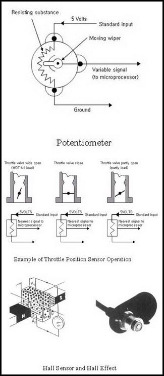
Position data for engine control is provided by throttle position sensor (TPS) Motor rotation Sensor (MRS) for some idling speed control system, EGR valve position sensor for EGR control system, crank position sensor (CKP), cam shaft position sensor, etc. Those sensors provide engine load condition information, and play important roles for deciding fuel injection and ignition timing, idling speed adjustment, EGR control, etc. Usually used principles for detecting position include potentiometer, magnetic resistance, Hall Effect, electronic induction, optical method, etc.The Potentiometer is a variable resistor made of resistance wire or resistance object, and it consists of power supply terminal and ground terminal, and signal terminal connected to moving wiper.
Potentiometer is a variable resistor that converts throttle opening of the valve to an electrical signal.
Resistance between power supply terminal and ground terminal is entire resistance of potentiometer, and does not vary. However resistance between signal terminal and ground terminal varies by moving the motion of wiper, generating divided voltage type signal out of constant supply voltage.
This potentiometer is used by sensors including TPS, MRS, EGR valve position sensor, etc, and also used by vane type air flow detector.
2) Throttle Position Sensor
1. ConfigurationTPS consists of housing assembly that enables sensor connection and sensor supply voltage approval and installation of collector ring, potentiometer, and O-ring, Collector ring that is connected with throttle valve axis, and rotates on variable resistance board of the potentiometer.
2. Operation Principle
Collector ring moves in linkage with throttle valve axis, and at end of the ring is connected brush. Brush is linked with throttle valve in moving on potentiometer ceramic board of the TPS on which resistor substance is applied, so as to provide linear output voltage in proportion with throttle valve opening.
3. Next Generation TPS
TPS measures rotation angle range of the throttle valve of a car. Collector ring brush installed in TPS moves in linkage with throttle valve side, contacting with resistance film surface that is made by applying resistance substance of thickness of several microns. When the brush rotates on the resistance film, the resistance value will vary to provide different output values that will be used for engine control. However the sensor actually installed on a car provides abnormal output characteristic due to various causes that are required to be analyzed and improved. In the sense of those efforts non-contact type of rotation angle measurement is suggested to replace conventional contact type measurement. Several manufacturers have completed or going developing those type rotation angle measuring sensors. Different types of non-contact rotation angle measurement are available. Among them those types using magnetic field characteristic of magnet and Hall Effect are widely used.
4. Throttle Position Sensor Checking
As TPS is a variable resistor, resistance shall be checked first. Disconnect throttle position sensor connector and measure resistance value between sensor supply power input terminal and ground terminal, and then compare it with relevant specified value of the engine.
As specified values differ by applicable model, you shall refer to relevant maintenance manual of the engine. When using voltage value for checking, with ignition switch on, check 5V voltage at sensor supply power input terminal. Sensor output voltage during idling is specified as approx. 0.4V~0.9V.
In addition slowly operate throttle valve, and observe output resistance or output voltage variation. If output signal does not vary or outside specified value, check for circuit-break and short, and replace throttle valve.
5. Failure Symptom
- Engine rpm rising and malfunction during idling.
- Poor acceleration during idling.
- Higher fuel consumption.
- Higher CO and HC emission.
3) Hall Sensor
(1) OutlineHall sensor depends on Hall Effect and widely used for CKP sensors and CMP sensors. The Hall Effect element is made of small, thin and plain semiconductor substance. When vertically installing conductor between two permanent magnets, and supplying power to the conductor, electrons in the conductor will be vertically deflected against supply current and magnets, and then one side will have surplus electrons and the other side will be short of electrons generating potential difference between two ends. It is called Hall Effect. The generated voltage is proportional to current and intensity of magnetic field, and then if the current is constant the output will be proportional magnetic intensity of the field. However the voltage is not strong enough, and then boosted before being used. The Hall sensor is similar to magnetic resistance type sensor. However magnetic resistance type sensor generates output even though engine is not operating and on the contrary Hall sensor does not have the same problem. CMP sensor is one of hall sensors, as it relies on Hall Effect.
(2) Cam Shaft Position Sensor Checking
1- Checking Procedure
If cam shaft position sensor is poor, consecutive injection will not occur correctly. In Melco system the sensor failure will make engine start-up literally impossible. If Cam shaft position sensors of Bosch or Siemens systems are failed, engine may start up.
However consecutive injection will not be correct and emission and mileage in cold start-up may be affected.
For cam shaft position checking, check power supply at terminal 3 using a digital volt-meter. In addition check connectors for connection, break and short.
2 - Failure Symptom
- No start-up for Delco systems.
- Engine start-up is possible. But emission and mileage may be poor in cold start-up.
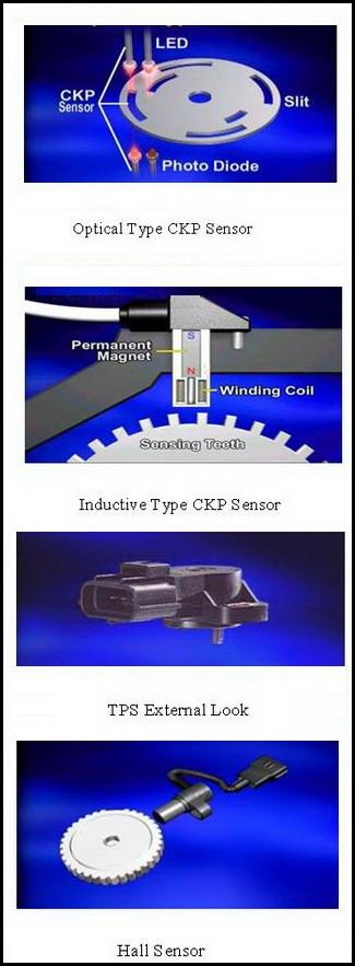
4) Inductive Type Crank Shaft Position Sensor
The sensor consists of sensor part that includes magnets and soft iron core winded by coil and toothed wheel that is designed to rotate in linkage with crankshaft. Toothed wheel has 58 teeth and two tooth gaps that are used for identifying cylinder No.1. Therefore are revolutions of toothed wheel make magnetic inductive type crank angel sensor generates 58 signals.When crankshaft rotates target wheel linked with crankshaft will rotate together, and then air gap between inductive CKP sensor wheel teeth varies periodically, that changes magnetism generated by permanent magnets. Then the magnetism variation will generate AC inductive electromotive force in soft iron core coil. The AC power will have lower amplitude when toothed wheel revolution is low and higher amplitude when toothed wheel revolution is high. When the sensor is at the opposite side of reference air gaps that have interval corresponding to two teeth, the AC power amplitude will rise up to provide detection of cylinder No. 1.
CKP sensor generates AC pulse per each tooth of toothed wheel, and consequently during one revolution of crankshaft, 58 AC pulses will be sent to ECM, that will then read the pulse signal to detect crank shaft angle.
5) Optical Rotation Sensor
(1) OutlineThe optical type CKP sensor consists of LED, photodiode and slit. Light emitted from LED is detected by photodiode through slit.
Then if slit rotates, the light will be interrupted and consequently photodiode will be unable to generate output signal.
(2) CKP Sensor Checking
If abnormal shock is felt during running or engine stops suddenly during idling, shake CKP sensor harness. If engine stops, check for poor contact.
In case of electronically inductive CKP sensor, if tachometer indicates "0" rpm during cranking, check CKP sensor and ignition system for defect.
If engine is cranked, tachometer indicates "0" rpm and engine does not start up, check ignition coil power TR in the ECM for defect.
In case of Optical CKP sensor, if CKP sensor outputs pulse signal with ignition switch "on" (no start-up), check CKP sensor and ECM for defect.
If engine does not start up and sensor output signal during cranking is "0" rpm, check CKP sensor and timing belt for defect.
If CKP sensor rpm is outside specified value and idling is possible, check coolant temperature sensor for failure.
Digital circuit tester is used to check sensor for circuit-break and short, and connector for contact condition. As CKP sensor provides periodic signal, it is required to check output waveform using oscilloscope.
(3) Failure Symptom
- Cranking is possible but hard to start engine.
- Hard to drive fuel pump.
- Spark plug is bard to generate spark.
- Engine sometimes stops during driving, and hard to restart engine.
Programming BMW F Series
Description
The position sensors provide engine load condition information, and play important roles for deciding fuel injection and ignition timing, idling speed adjustment, EGR control,and it when it fail it cause major Fault codes in the ECU of the engine .
Autohex II Reviews

AutoHex II
AutoHex Forum
Diagnosis and Coding