- Pressure Sensor
- |
- Sensors
- |
- Repair Basics
- |
- Technical Info
- |
- Car Tech Info
- |
- MicroTronik
Pressure Sensor
Pressure Sensor Types
Pressure Sensor Stracture
1) Intake Manifold Pressure Characteristic and MAP Sensor
Intake manifold is the route through that air and air/fuel mixture is inhaled to cylinder. At that time engine works as a pump that draws air into intake manifold.When engine is not operating, air will not flow, and then intake manifold pressure will be same as atmospheric pressure. When engine operates, throttle valve located in intake manifold will partly interrupt air flow. Then pressure in intake manifold will decrease getting lower than atmospheric pressure to generate partly vacuum in intake manifold. If engine were a perfect air pump and throttle valve is close, then intake manifold pressure will be absolute zero pressure, say perfect vacuum. However an actual engine cannot be a perfect pump, and perfect vacuum is not available, absolute pressure intake manifold is above zero. On the contrary when throttle valve is wide open, intake manifold pressure will be approx. atmospheric pressure. As described above, absolute pressure intake manifold will vary from relatively low value to just a little lower value than atmospheric pressure during engine operation.
We observe the pressure variation in the intake manifold when throttle valve position is constant. Intake manifold pressure fluctuates rapidly by consecutive suction of air by cylinders. Each cylinder sucks air when intake valves open and piston drops from TDC, and the intake manifold pressure will decrease. Air intake of this cylinder will be ended upon closure of intake valve, and intake manifold pressure will continue to rise until next cylinder begins to take air in. This process will be repeated to fluctuate the intake manifold pressure between each cycle of the cylinder, and pumping will be done from one cylinder to another. Each air intake of a cylinder action will occur once per two revolution of crank axis.
Actual engine control system requires average pressure in intake manifold, and torque generated at constant engine rpm will be approximately proportional to average value of intake manifold pressure. To say instantly changing pressure in intake manifold is not used for engine control, and then average value after filtering fluctuation components will be used. Engine control system has MAP sensor that measures absolute pressure in intake manifold.
2) Barometric Pressure
Barometric pressure is used as indicator of air density. When altitude rises, air density will decrease to reduce air intake rate. Therefore required air intake rate in order to maintain constant idle mileage will decrease as altitude rises. Similarly ignition timing shall be adjusted depending on air density, and is used for some cars to correct EGR operation of the valve and idling speed adjustment. As described Barometric pressure measurement is required to compensate air density variation by altitude or weather, and performed by BPS (Barometric Pressure Sensor). Recent trend is using a sensor built in ECM rather than separated BPS.3) Pressure Measuring Sensor
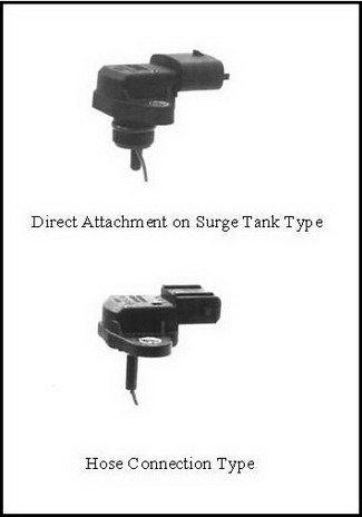
(1) ClassificationPressure sensors may be classified by installation method as direct attachment on surge tank type and hose connection type, and by purpose as MAP sensor, Map & IAT sensor, fuel tank pressure sensor, barometric pressure sensor, booster pressure sensor, EGR monitoring sensor, etc.
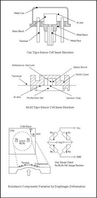
(2) Sensor Cell Structure
Inside MAP sensor, a pressure sensor cell is made by semiconductor process.
- By outside packaging:
Sensor cell may be classified into a can type and a plastic mold type. - By semiconductor process:
Bi-polar type and MOSFET type. - By feature adjusting method:
Laser trimming type and digital trimming type.
(3) Pressure Measuring Principle
Wheatstone bridge formed on diaphragm using piezo-resistance effect, generates voltage output by resistance components variation depending on approved pressure.
Piezo-resistance effect generates resistance components when area of the conductor or length varies, and provides linear resistance variation by physical variables applicable. As to silicon resistors, stress makes distortion at silicon lattice, and then changes edge status of conductive band or conclusive band, and that result changes of carrier number and movability varies electric resistance of the crystal.
When voltage is approved, compressive force will be applied to two resistors and tensile force to the other two resistors, changing resistance components in order to generate output voltage gap.
4) MAP Sensor
Terminal 1 is input of the sensor voltage with 5, terminal 2 is output terminal of the sensor, and terminal 3 is for grounding.Checking Procedure
Digital volt-meter is used to measure supply voltage of the sensor. With ignition switch on, measure output voltage at terminal 1 and decide if there is specified input voltage (5V). Sensor output signal can be measured at terminal 2 Then with ignition switch on (not starting up) output voltage shall be approx. 3.9~4.1V, and during idling output voltage shall be approx. 0.8~1.6V.
In case engine goes off sometimes, crank engine and shake MAP sensor harness. Then if engine goes off, it may be decided as a poor contact of the connector. If output value goes outside specified value with ignition switch on (no cranking), MAP sensor or ECM may be faulty. If MAP sensor output voltage is outside specified value but engine still idles, the following defects other than MAP sensor faults shall be checked. To say, poor connection between surge tank and hose, imperfect combustion inside cylinder, air leak at intake manifold, etc.
5) Failure Symptom
- Cranking is possible but hard to start engine.
- Engine malfunction during idling.
- Excessive fuel injection occurs to increase fuel consumption and degrade catalyzer.
Kia/Hyundai Key Teaching and PIN Code Calculation
Description
Pressure Sensors are imprtant sensors for the Car and it is connected to the Car ECU to measure various values , like Intake Manifold Pressure , Barometric Pressure,Turbo boost pressure,EGR pressure,Fuel pressure,Fuel vapor pressure,Exhaust gas pressure,and Second air pressure, depending on the same measuring principals .
Autohex II Reviews

AutoHex II
AutoHex Forum